OLT (Optical Line Terminal) optical line terminal, PON network consists of three parts: OLT, ODN and ONU. The OLT is a device on the service node side of the access network and is connected to the corresponding service node device through the SNI interface to complete service access to the access network.
OLT usually consists of the following parts:
1. Control board (also called main control board or super control unit). Generally, an OLT has two main and backup boards.
2. DC power board (power supply from the negative 48 volts of the switching power supply) is generally a main and backup board.
3. Fan unit (heat dissipation and environmental monitoring of main equipment, etc.)
4. Machine frame (or business frame)
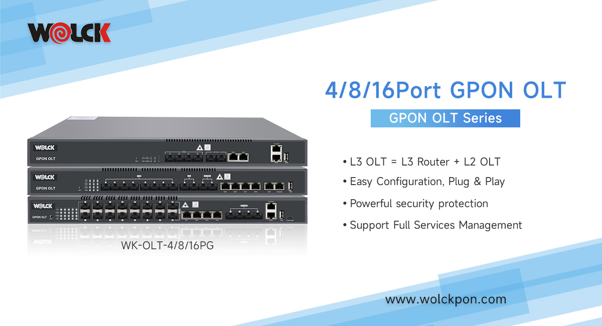
5. Uplink boards: GE optical interface board (including daughter board), integrated optical transceiver module. Generally, one board has 2 GE ports (currently 10GE is commercially available). The uplink boards are connected to the BRAS through transmission (OTN transmission) (Broadband remote access server) and other aggregation switches or directly connected to BRAS and other equipment and SR equipment. If you have IPTV services, you need to access the corresponding BNG equipment.) The uplink board has different transmission distances according to the optical module (no transmission is added in the middle). Reach 10-40KM.
6. Downlink board (also called business version or PON board). Generally, OLT equipment has a multi-port PON board (for example, a board has 8 PON ports). Each port goes through an optical splitter (not exceeding 1:64). ) to connect to the ONT terminal.
The downlink board transmission distance and attenuation have their limitations because of factors such as ranging between the ONT and OLT. For example, the 8-port GPON OLT interface board (including pluggable ClassB+ optical modules) requires the ODN transmission loss to be within -28db, and the 8-port GPON OLT interface board (including pluggable ClassC+ optical modules) requires the ODN transmission loss to be within -32db; However, considering later maintenance factors and other comprehensive reasons: it is required that the board of ClassB+ optical module be controlled within -25db in the initial project, and the board of ClassC+ optical module be controlled within -29db.
7. According to business needs, OLT can also insert (all can be mixed) TDM business version, Ethernet business version, 16-channel E1 business version and other boards.
8. The newly added OLT equipment must consider the full power consumption (calculated around 1400W) to calculate the size of the power cord and the size of the air switch (occupies 2 groups, one main and one backup). According to previous experience, generally the air switch is 63A; the wire diameter is 16mm² multi-stranded copper core wire (flame retardant), and the ground wire is 16mm² yellow and green copper core wire.
9. Pay attention to the occupied terminals of the OLT upstream so that there will be no problems during activation. The occupied terminals of the downlink must be carefully considered. The length of the pigtail must be measured (the optical jumper is provided by the manufacturer, and the power cord manufacturer provides it, but pay attention to the length). And the optical fiber jumper (the OLT side is the SC head (downstream) and the LC head upstream) is of flange type on the ODF side.


 What is the Role of EDFA in FTTH?
 The Difference Between AX1800 ONU and AX3000 ONU
 How are Huawei OLTs Classified?
 The Future Trend of Optical Line Terminals (OLTs)